
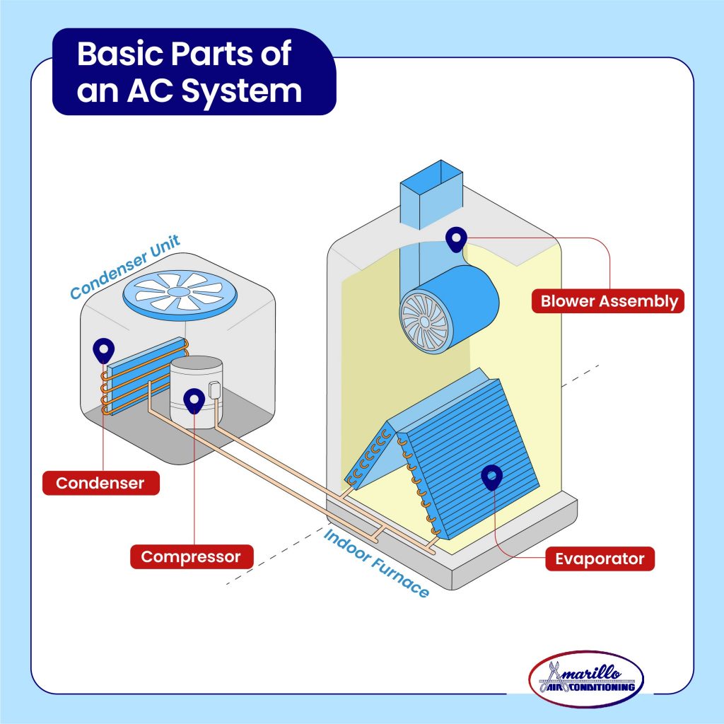
A central air conditioner consists of two main parts: the outdoor unit (condenser) and the indoor unit (air handler). Here’s a breakdown of the key components within each unit:
Outdoor Unit
- Compressor: The heart of the system. Compresses the refrigerant, increasing its pressure and temperature.
- Condenser: Hot, high-pressure refrigerant passes through the condenser coils, releasing heat to the outside air. The refrigerant cools and condenses into a liquid.
- Expansion Valve (or Metering Device): Controls refrigerant flow into the evaporator. It reduces the pressure of the liquid refrigerant, allowing it to expand and cool in the evaporator.
Indoor Unit
- Evaporator: Liquid refrigerant absorbs heat from the indoor air, causing it to evaporate into a gas. This cools the air that is circulated through your home.
- Air Handler (or Furnace): see the blower assembly in the diagram. Circulates air through your home’s ductwork. It contains a blower fan that pushes air across the evaporator coil (for cooling) or the furnace heat exchanger (for heating).
Appendix
- Ductwork: A network of channels distributing cooled or heated air throughout your home.
- Thermostat: Controls the system’s operation, turning it on or off based on the desired temperature.
Simplified Text Diagram:
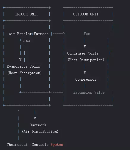
How the System Works:
- Return ducts draw warm air from your home into the air handler.
- This air is blown across the cold evaporator coils and cooled. The refrigerant inside the evaporator absorbs the heat.
- The cooled air is then distributed throughout your home through supply ducts.
- The heated refrigerant (now a gas) travels to the outdoor unit.
- The compressor compresses the refrigerant, increasing its pressure and temperature.
- The hot, high-pressure refrigerant flows through the condenser coils, releasing heat to the outside air. The refrigerant cools and condenses into a liquid.
- The liquid refrigerant flows through the expansion valve, which reduces its pressure and temperature.
- The cold, low-pressure refrigerant returns to the evaporator to repeat the cycle.
For more detailed information on how it works, click Central air conditioning system diagram.